|
|
Post by clickityclack on Aug 7, 2017 7:35:10 GMT -5
I'm working through the service manual to try to figure out why I don't have any spark on my 1975 H1. I purchased new moped coils which are all good, then I started checking the impedance on the 3 sections of the ignition rotor. I was getting an infinite value between the two sections of the inner rings and should be getting the same value when measuring between one of the inner rings and the ignition rotor area, however, I'm getting 17 megohms. As a new rotor on eBay is about $300, I want to verify that mine is actually bad before I purchase a replacement.
|
|
|
|
Post by mraxl on Aug 7, 2017 8:31:55 GMT -5
I'm working through the service manual to try to figure out why I don't have any spark on my 1975 H1. I purchased new moped coils which are all good, then I started checking the impedance on the 3 sections of the ignition rotor. I was getting an infinite value between the two sections of the inner rings and should be getting the same value when measuring between one of the inner rings and the ignition rotor area, however, I'm getting 17 megohms. As a new rotor on eBay is about $300, I want to verify that mine is actually bad before I purchase a replacement. Your terminology is a bit off... the ignition rotor is a hunk of metal with no wiring. The alternator rotor has brushes to ign coils making contact with rotor face to make a ground connection as the rotor turns. To see if that is working as it should... put a meter lead on a coil "-" terminal, the other to ground. Now rotate the motor 360deg. As the motor turns the resistance should drop to near zero, then infinity again. Repeat again for next coil. |
|
|
|
Post by givr on Aug 7, 2017 8:40:39 GMT -5
Tell us more about the moped coils. Do they have 2 grounding leads for the primary and secondary windings? I'm not a 2 pickup ignition expert but the Glenn's manual is pretty adamant about using OEM coils otherwise damage to the distributor can result.
|
|
|
|
Post by clickityclack on Aug 7, 2017 14:23:01 GMT -5
I tried to upload a picture which described how I got the rotor electrical measurements, but the forum seems to think it's over the size limit, even thought the picture is 164kb, much lower than the 1mb space limit. See picture here, ibb.co/nFrO1aI understand that the rotor is a big hunk of metal and the brushes ride on it. I was simply following the instructions found from a service manual scan which specified the inner slip rings need to have an infinite value and the value when checking between the area behind the rotor and one of the inner slip rings. I've checked the brushes, which were all well within the wear limit and the pickups, which ohm-ed within spec. The moped coils I purchased are 1 wire coils, but I should be able to use them as 2 wire coils buy isolating the coil from grounding through the frame (as the moped coils were designed to do) and having them use the rotor ground so I don't have a wasted spark ignition. givr, my engine doesn't have a distributor, per say, but does have the 5 brushes that behave like a distributor. My bike has the late 1975 CDI setup. |
|
|
|
Post by Jim on Aug 7, 2017 14:46:09 GMT -5
Josh, if you hold the tip of one meter probe between the thumb and forefinger of your left hand and the tip of the other lead the same way in your right hand, you'll probably see much less resistance than 17 megohms. As I said in the email, unless something causes it to go much lower, that extremely small conductivity won't have any effect on the ignition system.
|
|
|
|
Post by mraxl on Aug 7, 2017 15:19:01 GMT -5
I understand that the rotor is a big hunk of metal and the brushes ride on it. I was simply following the instructions found from a service manual scan which specified the inner slip rings need to have an infinite value and the value when checking between the area behind the rotor and one of the inner slip rings. This is your ignition rotor: 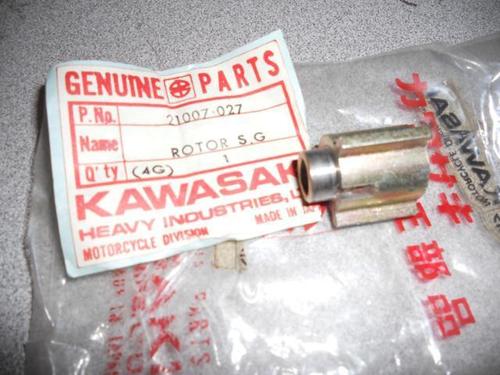 If you will check the resistance of the assembled rotor/stator from the blu/blk/grn at what should be ignition coil "-" as I stated earlier you will know if the alternator rotor is causing your "no spark" problem.... which is extremely unlikely. |
|
|
|
Post by III on Aug 7, 2017 16:44:15 GMT -5
I understand that the rotor is a big hunk of metal and the brushes ride on it. I was simply following the instructions found from a service manual scan which specified the inner slip rings need to have an infinite value and the value when checking between the area behind the rotor and one of the inner slip rings. This is your ignition rotor: If you will check the resistance of the assembled rotor/stator from the blu/blk/grn at what should be ignition coil "-" as I stated earlier you will know if the alternator rotor is causing your "no spark" problem.... which is extremely unlikely. That is the signal generator as Dale points out. Below is a shot of it on the ROTOR. I thought the slip ring issues were only on the early H1 iggy systems??? 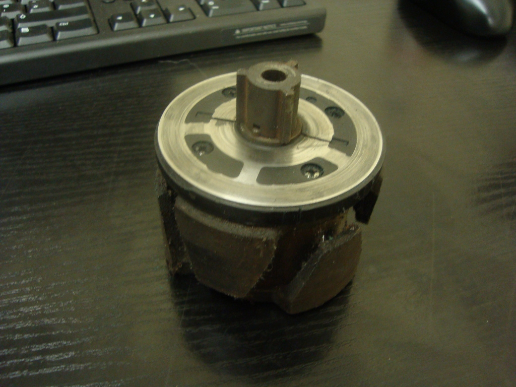 You really should get more familiar with your models components. You can start here..... kawatriple.com/partid/electrics/electrics.htm for electricals But this is where your really should start.... kawi2strokes.com/forum/viewtopic.php?f=34&t=5 |
|
|
|
Post by Jim on Aug 7, 2017 17:08:40 GMT -5
Actually, the two black plastic things are the signal generators, by the terminology in most places of the Kawasaki manual. The three lobed iron thing is the "signal generator rotor". It's not completely consistent though.
|
|
|
|
Post by clickityclack on Aug 8, 2017 10:49:59 GMT -5
Thanks for your input guys.
Took another look at the bike last night. Found that when rotating the engine slowly and checking the impedance at the ignition coil ground as 12V feed, the lowest resistance I saw was about 160 ohms across all three wires. I found the rotor face was dirty, tried cleaning it up with some rubbing alcohol but that was going to take forever, used a little bit of metal polish and a buffing attachment for my Dremel and got the face of the rotor really clean and smooth. I'm now seeing a measurement of 8 megohms from the inner slip rings to the rotor area. I haven't had a chance to rotate the engine and check the resistance on the brushes, will try to get that done today. May take some pictures to show you guys what I'm doing since the terminology is a bit confusing.
|
|
|
|
Post by mraxl on Aug 8, 2017 11:48:26 GMT -5
Thanks for your input guys. Took another look at the bike last night. Found that when rotating the engine slowly and checking the impedance at the ignition coil ground as 12V feed, the lowest resistance I saw was about 160 ohms across all three wires. I found the rotor face was dirty, tried cleaning it up with some rubbing alcohol but that was going to take forever, used a little bit of metal polish and a buffing attachment for my Dremel and got the face of the rotor really clean and smooth. I'm now seeing a measurement of 8 megohms from the inner slip rings to the rotor area. I haven't had a chance to rotate the engine and check the resistance on the brushes, will try to get that done today. May take some pictures to show you guys what I'm doing since the terminology is a bit confusing. I'm not sure I understand what you are saying.... or whether or not you are testing with the brush plate assembled to rotor. Assembled: -the shaft end of the rotor measured to ground (battery (-)) should be zero ohms... if not the ground strap wire from motor to frame is missing or battery ground wire is not connected to frame -the slip rings on the rotor should measure zero ohms to frame ground.. black wire from dual pin connector to blk/yel wire -the blu/blk/grn wires from the ignition coil should measure zero ohms as the engine is rotated thru 360deg.. if not the brushes are not making good contact with rotor slip rings (maybe from the polish you used to clean them) The resistance measured from the (+) terminal of the ignition coil to each blu/blk/grn coil connection points should be about 1.0 ohms... if not the coil you have won't work for long and may damage the CDI unit. (Don't know why you would not use stock coils?) |
|
|
|
Post by Jim on Aug 24, 2017 22:06:56 GMT -5
Any progress?
|
|
|
|
Post by clickityclack on Oct 27, 2017 11:08:46 GMT -5
Sorry for the delay, had a bunch of other projects to work on and just getting back to the H1.
Since I had already purchased an NOS ignition rotor, I worked on installing that last night. My rotor bolt sheared when tightening it, thankfully a left-handed drill was able to remove the chunk of bolt that got stuck in the crank. Hoping to make a Home Depot trip today to get a replacement bolt and will put everything back together when I get home.
Another thing I noticed was oil in the ignition area, which I thought was a bit strange. Thinking it's either coming from a leak in the case or the crank seal is bad, though it looks like it was recently replaced. Anyone else ever seen that?
|
|
|
|
Post by Jim on Oct 27, 2017 12:16:28 GMT -5
Yes, and if the crank seal is leaking after being recently replaced, you should yank the crank up and down and forward and back, and see if you can see any movement. If so, your crank bearing is shot and letting the end of the crank move around.
|
|